OPTICAL ALIGNMENT OF DRIVE SYSTEM

Large and small drive systems have benefited from the applications of optical alignment technology.

DRIVE SYSTEM

Optical tooling provides the means of viewing the entire drive system's centerline as opposed to conventional "coupling to coupling" methods. This is extremely beneficial with lengthy drives containing multiple components and couplings.

Optical equipment may require much less setup time relative to conventional mechanical methods. Readings are taken directly at bearing points. This type of inspection, using optical tooling, eliminates the need to "break" couplings or rotate the drive unit. The optical readings provide direct information regarding the amount of movement necessary to correct misaligned conditions. All of these factors make optical alignment a very economical and sensible solution for drive alignment.

The basic setup to optically align drive systems is shown above. First, the radius of an inspection point is mechanically measured. Using a precision optical scale, the distance from the inspection point's surface is measured to the optical line of sight. The total distance of the inspected point's centerline to the optical plane can then be calculated.

Because the optical line of sight provides a true flat plane, mathematical differences in the measurements indicate centerline misalignment. The ideal alignment condition is having the drive system's centerline straight and coincident in both the horizontal and vertical planes.

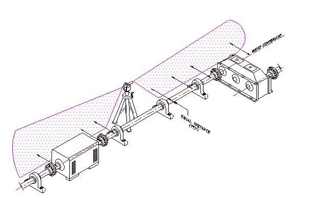
As you can see, optical alignment, as applied to drive systems, can compare centerline offsets and straightness within thousandths of an inch due to its measuring abilities. Because optics provides a flat and straight plane over long distances, horizontal and vertical adjustments may be accomplished to minimize offset alignment and virtually eliminate angular misalignment at couplings.