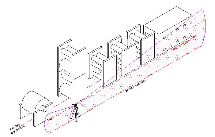
Once new machinery has been optically leveled, component or module offsets and straightness must be set. The illustration below depicts a typical optical tooling setup necessary to perform this work. Using the established optical planes, precision optical scales are placed on machined surfaces to measure differences in straightness and alignment. Individual components or assemblies are aligned straight and parallel relative to the machine centerline and baseline. Not all of the components may be identical in cross-machine width; therefore, the dimensional widths of each unit are taken into consideration when performing alignments of this nature.